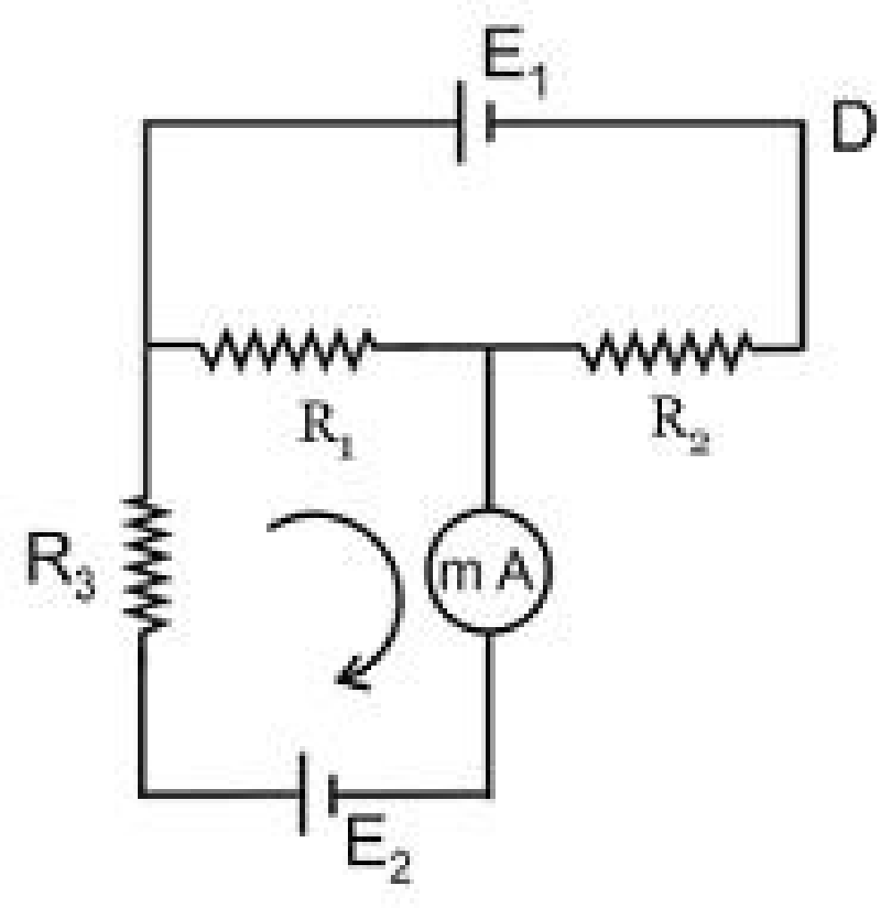
The circuit shown in the figure contains three resistors R 1 = 100 Ω Ω , R 2 = 50 Ω Ω and R 3 = 20 Ω Ω and cells of E.M.F.s E 1 = 2 V and E 2 . The ammeter indicates a current of 50 mA. Find the E.M.F (in V) of the second cell. (The internal resistance of the ammeter and of the cell should be neglected)
Text Solution
Verified by ExpertsThe correct answer is:
CHECK THE SOLUTION.
(4)
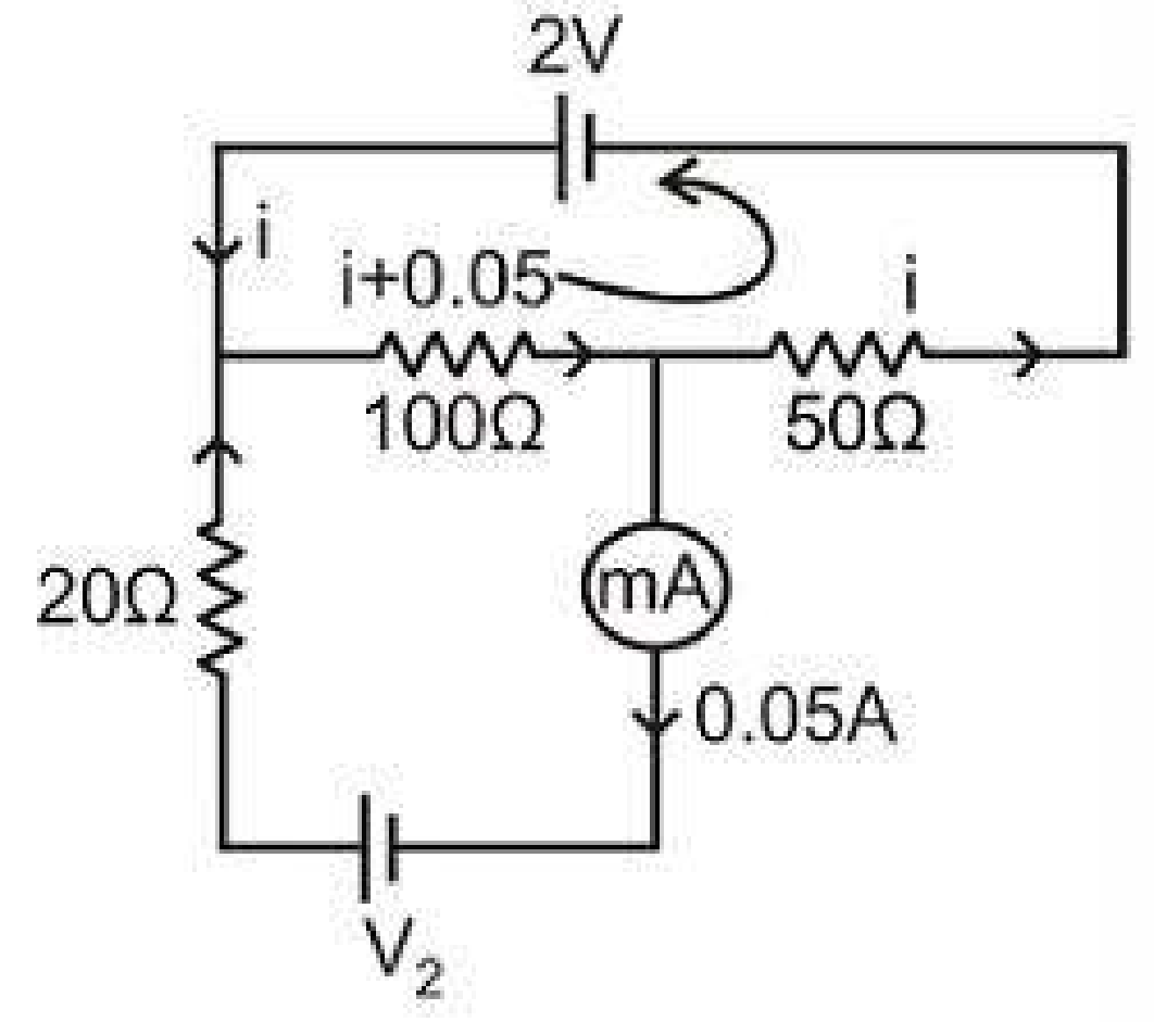
Using s KVL:


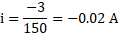

So, the direction of  is opposite to what we have assumed. If we redraw the circuit.
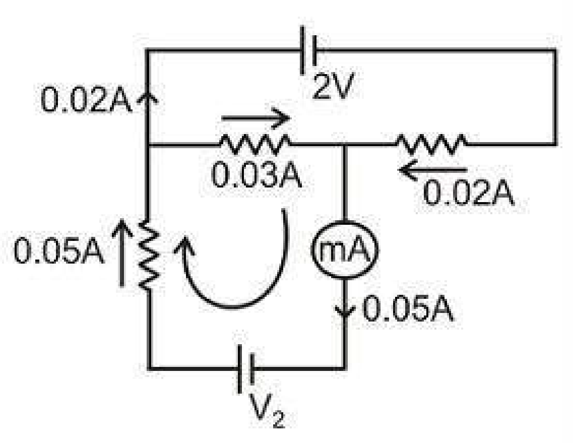
Using KVL:



Prepare Smarter with CGP Edu
Get practice questions, solutions, and test series in one place.
Write a Review
Share your experience with this question and solution.
Commentary
Send your comment, doubt, correction, or feedback to admin.
Similar Questions
Explore conceptually related problems
The voltage of clouds is 4 x 10 6 V with respect to ground. In a lightning strike lasting 100 ms, a…
A constant 60 V supply is connected across the two resistors as shown in diagram. Calculate the rea…
In the given circuit, Reading of ammeter is 1 A. If each of the 4 Ω Ω resistor is replaced by 2 Ω Ω…
Twelve resistors each of resistance are connected as shown in the figure. Net resistance between p…
Given . What is total resistance in parallel with possible percentage error?
The maximum and the minimum equivalent resistance obtained by combining identical resistors of res…