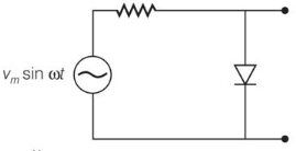
The output of the given circuit in figure given below, is
Text Solution
Verified by ExpertsC
Due to forward biasing during positive half cycle of input AC voltage, the resistance of  junction is low. The current in the circuit is maximum. In this situation, a maximum potential difference will appear across resistance connected in series of circuit. This result into zero output voltage across
  junction. Similarly during negative half cycle of AC voltage, the
  junction is reverse biased. The resistance of
  junction becomes high which will be more than resistance in series. That is why, there will be voltage across
  junction with negative cycle in output.
Prepare Smarter with CGP Edu
Get practice questions, solutions, and test series in one place.
Write a Review
Share your experience with this question and solution.
Commentary
Send your comment, doubt, correction, or feedback to admin.
Similar Questions
Explore conceptually related problems