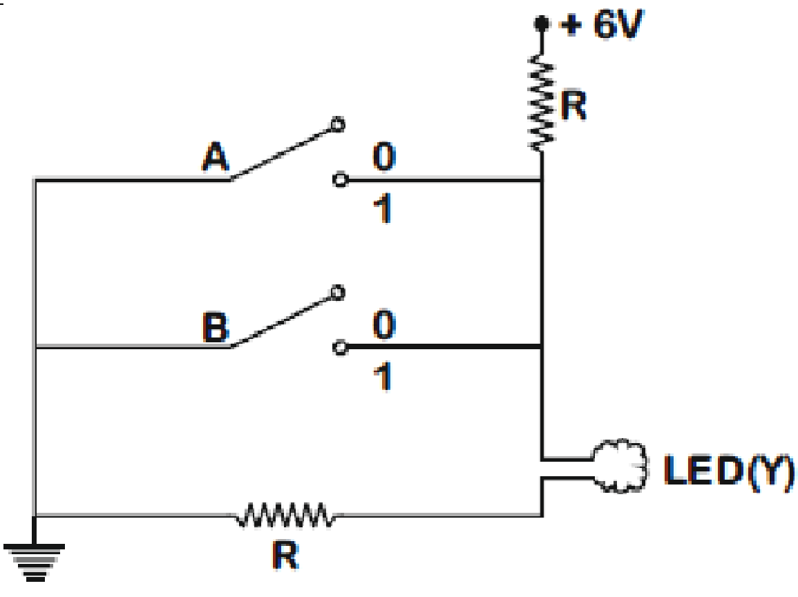
The circuit diagram shown here corresponds to the logic gate
Text Solution
Verified by ExpertsNOT AVAILABLE
Now,
For the given case, consider when the output is low (Key is open) it can be denoted as '0'.
Similarly, when the output is high (Key is closed) it can be denoted as '1'.
Hence,
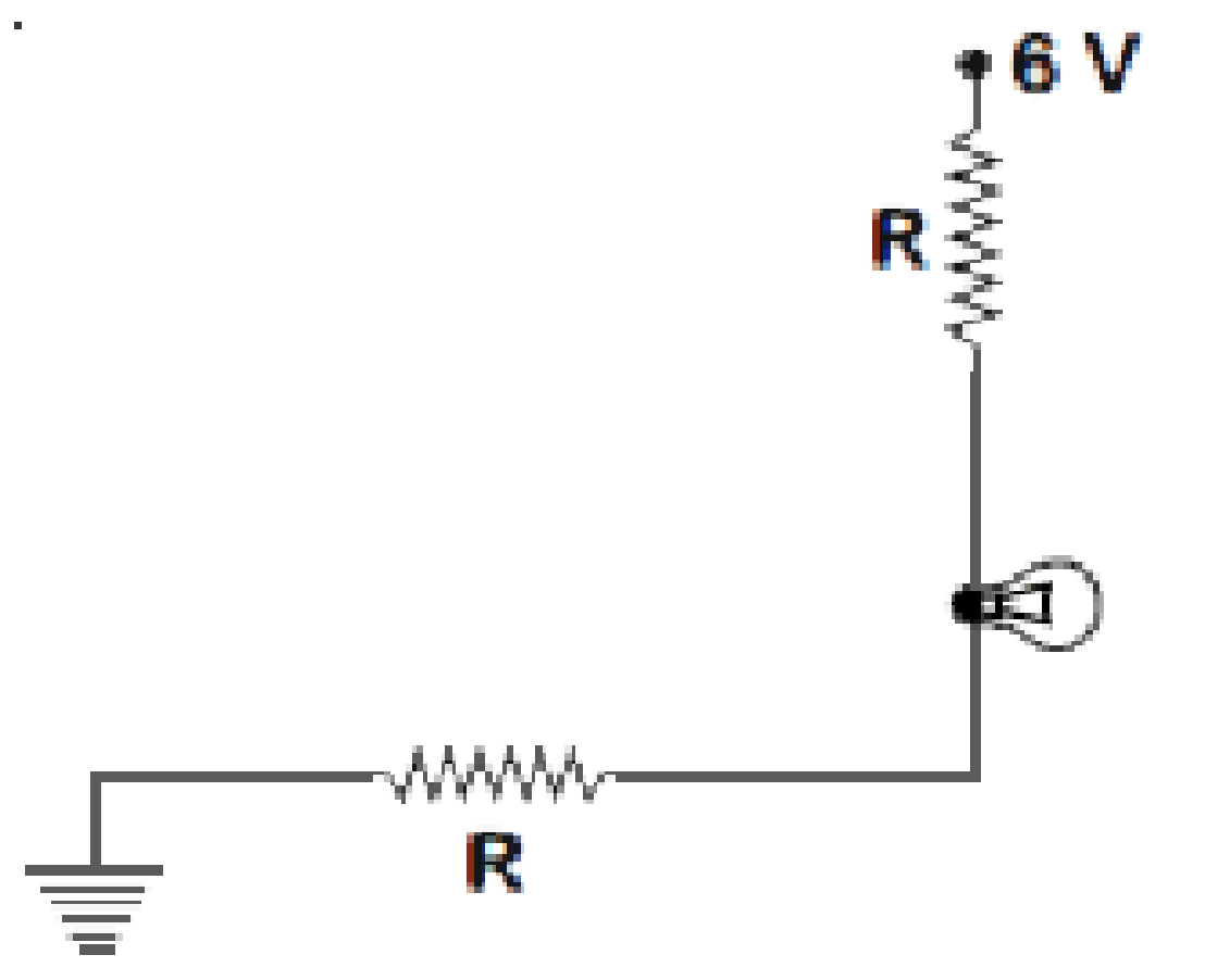
Case-1:
When, A = 0, B = 0
LED will glow
 Y = 1
Y = 1
Case-2:
A = 0, B = 1
No current will through LED
 Y = 0
Y = 0
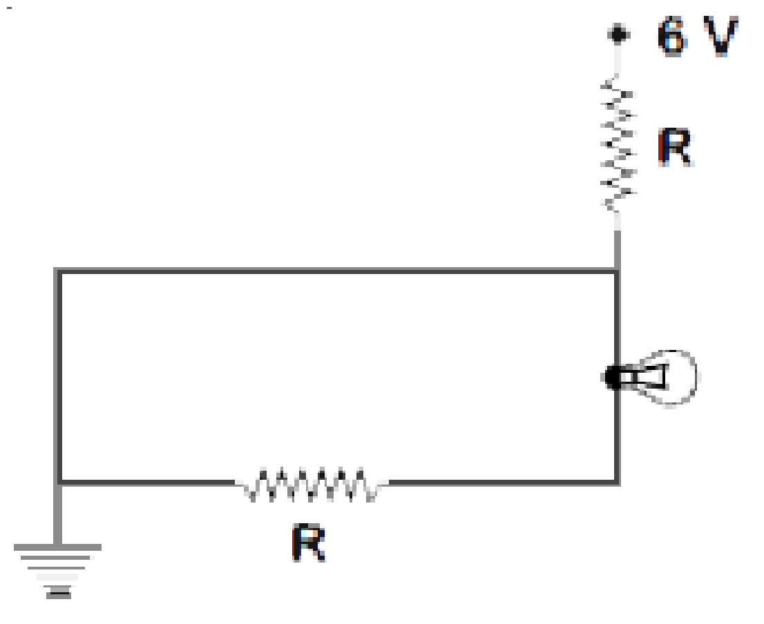
Case-3 : A = 1, B = 0
Again no current will through LED
 Y = 0
Y = 0
Case-4 : A = 1, B = 1
Again Y = 0
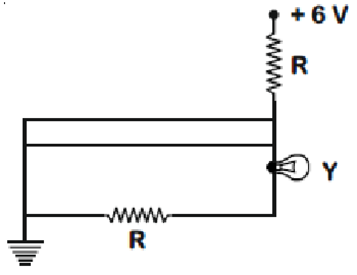
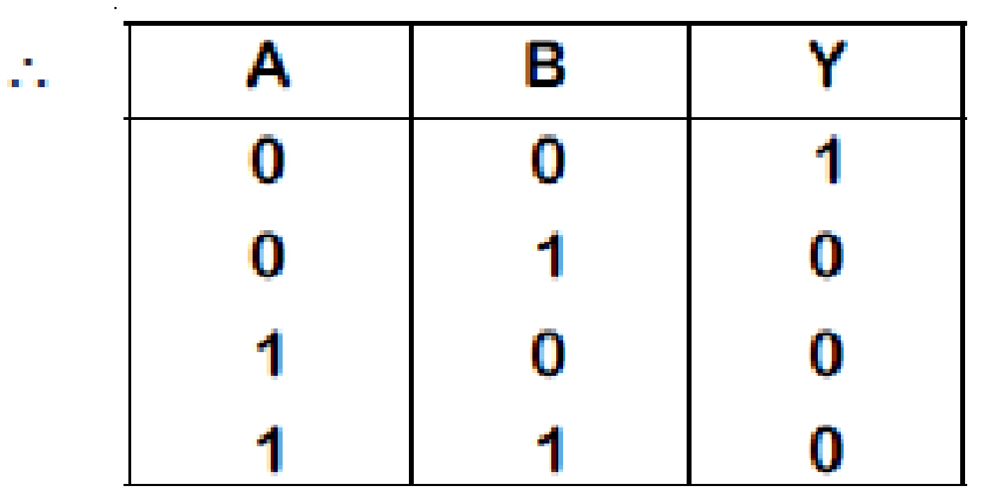
Hence corresponding circuit will behave as NOR gate,
──────────────────────────────────────────────────────────────────────────────────────────
Prepare Smarter with CGP Edu
Get practice questions, solutions, and test series in one place.
Write a Review
Share your experience with this question and solution.
Commentary
Send your comment, doubt, correction, or feedback to admin.
Similar Questions
Explore conceptually related problems