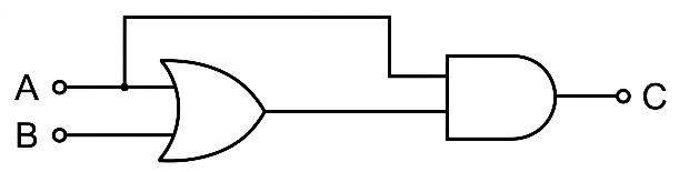
The truth table corresponding to the circuit given below is:
A | B | C |
0 | 0 | 0 |
0 | 1 | 0 |
1 | 0 | 1 |
1 | 1 | 1 |
A | B | C |
0 | 0 | 1 |
1 | 0 | 0 |
0 | 1 | 0 |
1 | 1 | 0 |
A | B | C |
0 | 0 | 1 |
0 | 1 | 0 |
1 | 0 | 0 |
1 | 1 | 0 |
A | B | C |
0 | 0 | 0 |
1 | 0 | 0 |
0 | 1 | 0 |
1 | 1 | 1 |
Text Solution
Verified by ExpertsThe correct answer is:
A
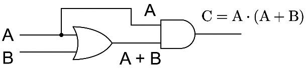
A | B | C | |
0 | 0 | 0 | 0 |
1 | 0 | 1 | 1 |
0 | 1 | 1 | 0 |
1 | 1 | 1 | 1 |

Prepare Smarter with CGP Edu
Get practice questions, solutions, and test series in one place.
Write a Review
Share your experience with this question and solution.
Commentary
Send your comment, doubt, correction, or feedback to admin.
Similar Questions
Explore conceptually related problems
The Boolean expression can be realised with which of the following gate configurations.
Consider a n-type semiconductor in which and are number of electrons and holes, respectively.
Choose the correct logic circuit for the given truth table having inputs A and B.
InputsOutputABY00…
Consider the following logic circuit.
The output is when:
In the digital circuit shown in the figure, for the and values are.
In the following circuit, the reading of the ammeter will be (Take Zener breakdown voltage )