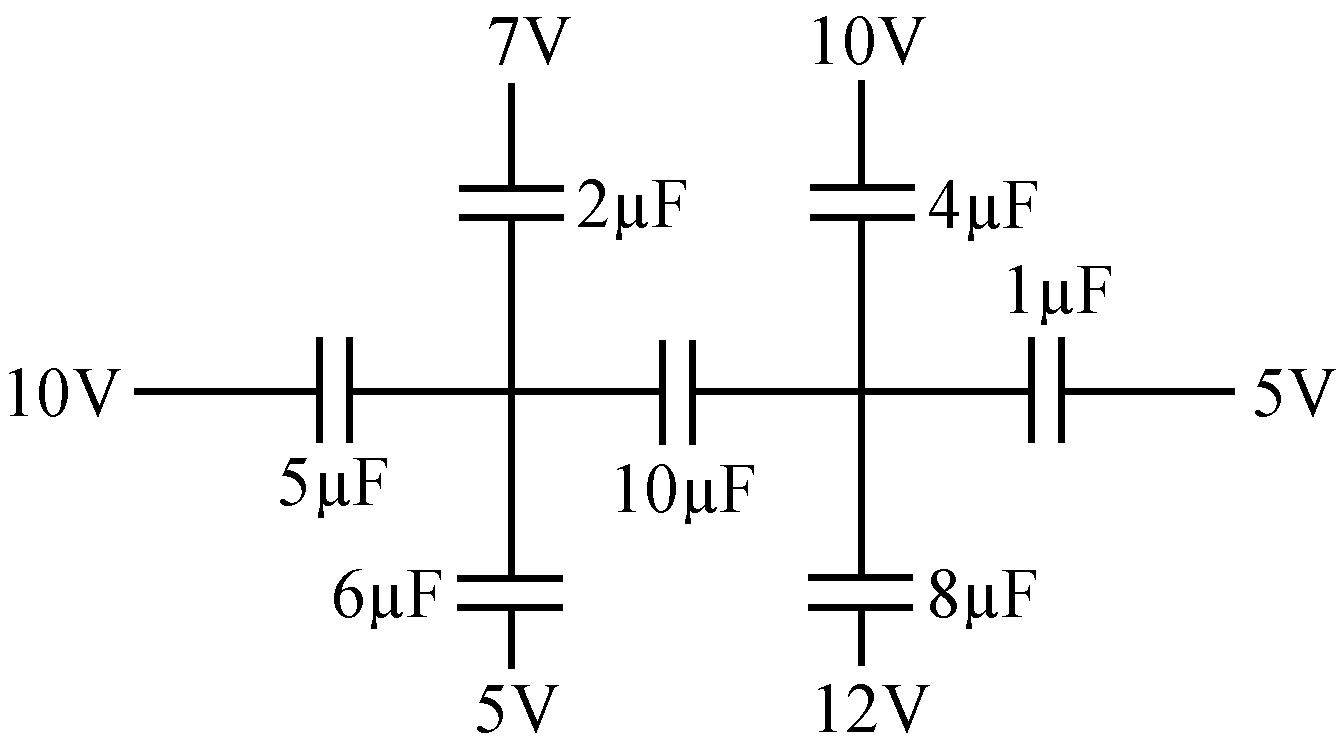
Find the charge flowing through the capacitor marked 10 µF. The potential at different points are indicated in diagram.
Text Solution
Verified by ExpertsCHECK THE SOLUTION.
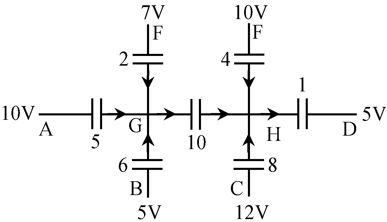
Sol. The circuit diagram is shown in fig.
There are two nodes – G and H.
The charge flow is as indicated in the diagram
Consider the node G.
Charge entering the node = charge leaving the node.
Charge enters through AG, BG, FG and leaves through GH.
Assume the potential at the nodal point G be V G and H be V H .
Charge entering the node = 5(10 – V G ) + 6(5 – V G ) + 2(7 – V G )
= 94 – 13V G ….. (1)
Charge leaving the node = 10(V G – V H ) ….. (2)
Equating (1) and (2),
94 – 13V G = 10(V G – V H )
23V G – 10 V H = 94 ….. (3)
Consider the node H.
Charge entering the node = charge leaving the node.
Charge enters through GH, EH, CH and leaves through HD.
Charge entering the node = 10(V G – V H ) + 4(10 – V H ) + 8(12 – V H )
= 136 + 10V G – 22V H ….. (4)
Charge leaving the node = I(V H – 5) ….. (5)
Equating (4) and (5),
136 + 10V G – 22V H = I(V H –5)
23V H + 10V G = 141 ….. (6)
The number of unknowns is two and we have two equations to solve. Therefore, V G and V H can be found.
Solving the equations (3 and (6),
V G = 5.679 V
V H = 3.661 V
Charge flowing through the capacitor across
GH = C(V G – V H )
= (10 × 10 –6 ) × (5.679 – 3.661) = 2.018 × 10 –5 coulomb.
Therefore, charge flowing across the capacitor GH = 2.018 × 10 –5 Coulomb.
Prepare Smarter with CGP Edu
Get practice questions, solutions, and test series in one place.
Write a Review
Share your experience with this question and solution.
Commentary
Send your comment, doubt, correction, or feedback to admin.
Similar Questions
Explore conceptually related problems