An electric circuit shown in figure has a negligible small active resistance. The left-hand capacitor was charged to a voltage V 0 and then at the moment t = 0 the switch Sw was closed. Find the time dependence of the voltages in left and right capacitors.
Figure
Text Solution
Verified by ExpertsCHECK THE SOLUTION.
Sol. The problem is based upon charging and discharging of capacitors through inductor.
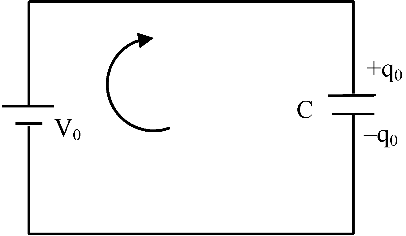
When t < 0, capacitor is in steady state (shown in figure a)
According to loop rule, V 0 –  = 0
= 0
q 0 = CV 0
At t = 0, charge on left capacitor is q 0 = CV 0 …(i)
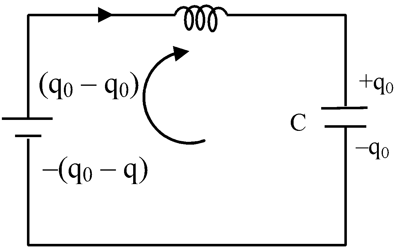
At t = 0, current in the circuit is zero. But charge on right capacitor is zero at t = 0. Switch is closed at t = 0, left capacitor starts to discharge through inductor and right capacitor starts charge. Let t an instant t, current in the circuit is I and charge on right capacitor is q.
The situation of circuit is shown in figure b.
According to loop rule,  – L
– L  –
–  = 0
= 0
 –
–  – L
– L  = 0
= 0
(q 0 – 2q) = LC 
–2  = LC
= LC 
–2I = LC 
 = –
= – 
The equation is similar to simple harmonic motion.
I = Asin( ω t + φ )
Here ω = θ 
At t = 0, I = 0
∴ sin φ = 0
∴ φ = 0
∴ I = Asin ω t
or  = Asin ω t
or  =
= 
∴ q =  [1 – cos ω t]
When t > 0, charge on right capacitor increase and current in the circuit also increases. When the charges on both capacitors are same, voltages of both capacitors are same. So current is maximum.
According to conservation principle of energy,
 = Loss in electrostatic energy.
or  =
=  –
– 
or  =
= 
 =
= 
∴ I 0 = 
Here I 0 is the maximum value of current in the circuit.
But I max = A = I 0 = 
∴ q =  [1 – cos ω t]
or q = 
 [1 – cos ω t]
or q =  [1 – cos ω t]
The voltage of left capacitor is
V 1 =  =
=  [ 1 + cos ω t]
And the voltage of right capacitor is
V 2 =  =
=  [1 – cos ω t]
Here ω = 
Prepare Smarter with CGP Edu
Get practice questions, solutions, and test series in one place.
Write a Review
Share your experience with this question and solution.
Commentary
Send your comment, doubt, correction, or feedback to admin.
Similar Questions
Explore conceptually related problems