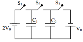
In the circuit shown in the figure, there are two parallel plate capacitors each of capacitance C. The switch S 1 is pressed first to fully charge the capacitor C 1 and then released. The switch S 2 is then pressed to charge the capacitor C 2 . After some time, S 2 is released and then S 3 is pressed. After some time.
Text Solution
Verified by ExpertsCHECK THE SOLUTION.
(b, d)
Sol. When switch S 1 is released charge on C 1 is 2CV 0 (on upper plate)
When switch S 2 is pressed charge on C 1 is CV 0 (on upper plate) and charge on C 2 is CV 0 (on upper plate)
When switch S 2 is released and switch S 3 pressed charge on C 1 is CV 0 (on upper plate) and charge on C 2 is – CV 0 (on upper plate)
Prepare Smarter with CGP Edu
Get practice questions, solutions, and test series in one place.
Write a Review
Share your experience with this question and solution.
Commentary
Send your comment, doubt, correction, or feedback to admin.
Similar Questions
Explore conceptually related problems