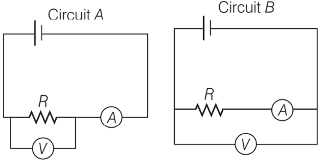
For the circuit A and B as shown in the figure, identify the correct option.
Text Solution
Verified by ExpertsB
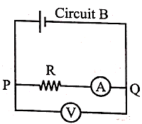
Circuits A represents an ammeter, which is used to measured the current it is a low resistive device, 80 that it does not affect the circuit. It is connected in series with resistor. Similarly, V represents a voltmeter, which is used to measure the potential drop. It is usually a high resistive device, so that the negligible current passes through it. Thus, does not affect current passing through the resistor. It is connected in parallel with to the resistor. This implies that, these devices are used measure. Current and voltage drop across a resistor, without actually affecting any of these quantities because of their addition in the circuit. So, the given circuits A and B as shown below.
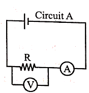
We can conclude that the circuit A has been correctly connected. Therefore, it can be used to measure R accurately, which can be calculated with the help of ammeter and voltmeter reading as,
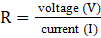 [From Ohm's law]
However, when the arrangement of ammeter and voltmeter is as per given in circuit B. The circuit then is usually used for measuring higher resistance as compare to circuit A.
Prepare Smarter with CGP Edu
Get practice questions, solutions, and test series in one place.
Write a Review
Share your experience with this question and solution.
Commentary
Send your comment, doubt, correction, or feedback to admin.
Similar Questions
Explore conceptually related problems