Published by:
CGP EDU Academic Team
Published on: September 12, 2026
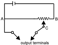
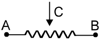
Connect a battery to the terminals and complete the circuit diagram so that it works as a potential divider meter. Indicate the output terminals also.
Text Solution
Verified by ExpertsThe correct answer is:
A
Step 1: Understand the setup of a potential divider. A potential divider usually consists of two resistors (in this case represented by the zig-zag line) connected in series with a voltage source.
Step 2: The basic formula for a potential divider is:
$$ V_{out} = V_{in} \times \frac{R_2}{R_1 + R_2} $$
where $V_{in}$ is the input voltage from the battery, $R_1$ is the resistance across terminals A, and $R_2$ is the resistance across terminals B.
Step 3: Connect a battery to the circuit with the positive terminal connected to point A and the negative terminal connected to point B. Ensure that point C is the output terminal where the voltage is measured.
Step 4: Thus, connect the circuit as shown in the diagram, with A being one terminal before the first resistor and B after the second resistor, while C can be connected between the resistors to measure the voltage across one of them.
Therefore, A.
Step 2: The basic formula for a potential divider is:
$$ V_{out} = V_{in} \times \frac{R_2}{R_1 + R_2} $$
where $V_{in}$ is the input voltage from the battery, $R_1$ is the resistance across terminals A, and $R_2$ is the resistance across terminals B.
Step 3: Connect a battery to the circuit with the positive terminal connected to point A and the negative terminal connected to point B. Ensure that point C is the output terminal where the voltage is measured.
Step 4: Thus, connect the circuit as shown in the diagram, with A being one terminal before the first resistor and B after the second resistor, while C can be connected between the resistors to measure the voltage across one of them.
Therefore, A.
Prepare Smarter with CGP Edu
Get practice questions, solutions, and test series in one place.
Write a Review
Share your experience with this question and solution.
Commentary
Send your comment, doubt, correction, or feedback to admin.
Similar Questions
Explore conceptually related problems
The current through the ammeter shown in figure is 1 A. If each of the 4 Ω Ω resistor is replaced b…
The meter-bridge wire AB shown in figure is 50 cm long. When AD = 30 cm, no deflection occurs in th…
The potential gradient of a potentiometer wire is defined as
The unit of potential gradient is
The length of the potentiometer wire is kept larger so that the value of potential gradient may
For the same potential difference, a potentiometer wire is replaced by another one of a high specif…