In the circuit shown in fig. E, F, G and H are cells of emf 2, 1, 3 and 1 volts and their internal resistances are 2, 1, 3 and 1 ohm respectively. Calculate.
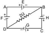
(i) The potential difference between B and D is given by  Volt then valu of n will be.
(ii) The ratio of potential difference across the terminals of the cell G to cell H is given by  the value of n will be.
Text Solution
Verified by ExpertsCHECK THE SOLUTION.
[(i) 11, (ii) 19]
Sol Applying Kirchhoff ’ s second law in loop ADBA:
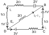
2 – 2i 1 – i 1 – 1 – 2(i 1 – i 2 ) = 0 .........
Similarly applying Kirchhoff ’ s second law in loop BDCB
2(i 1 – i 2 ) + 3 – 3i 2 – i 2 – 1 = 0.........
Solving Equation and we get,
i 1 =  , i 2 =
  and i 1 – i 2 = –
(i) Potential difference between B and D.
V B + 2(i 1 – i 2 ) = V D
V B – V D = – 2(i 1 – i 2 ) =  volt
volt
(ii) V G = E G – i 2 r G = 3 –  × 3 =
× 3 =  volt
volt
V H = E H + i 2 r H = 1 +  × 1 =
× 1 =  volt
volt
Prepare Smarter with CGP Edu
Get practice questions, solutions, and test series in one place.
Write a Review
Share your experience with this question and solution.
Commentary
Send your comment, doubt, correction, or feedback to admin.
Similar Questions
Explore conceptually related problems