Published by:
CGP EDU Academic Team
Published on: September 12, 2026
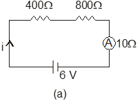
Two resistors, 400 Ω Ω , and 800 Ω Ω are connected in series with a 6 V battery. It is desired to measure the current in the circuit. An ammeter of 10 Ω Ω resistance is used for this purpose. The reading of ammeter will be
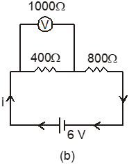
A. Similarly, if a voltmeter of 1000 Ω Ω resistance is used to measure the potential difference across the 400 Ω Ω resistor, the reading of voltmeter is
V. Then the value of N and P are:
Text Solution
Verified by ExpertsThe correct answer is:
A
Step 1: Calculate the total resistance in the circuit before connecting the ammeter.
The resistors are connected in series:
Rtotal = R1 + R2 = 400 Ω + 800 Ω = 1200 Ω.
Step 2: Determine the current in the circuit without the ammeter.
Using Ohm's Law:
I = \frac{V}{R} = \frac{6 \text{ V}}{1200 \text{ Ω}} = 0.005 ext{ A} = 5 ext{ mA}.
Step 3: Consider the ammeter in series. The ammeter has a resistance of 10 Ω.
The new total resistance:
Rtotal = R1 + R2 + Rammeter = 1200 Ω + 10 Ω = 1210 Ω.
Step 4: Calculate the current with the ammeter connected.
I' = \frac{V}{R'} = \frac{6 ext{ V}}{1210 ext{ Ω}} \approx 0.004964 ext{ A} = 4.964 ext{ mA}.
Step 5: Now, for the voltmeter, its resistance is 1000 Ω connected across the 400 Ω resistor, reducing the total resistance in that segment.
The equivalent resistance for the 400 Ω resistor (R1) and the voltmeter (Rv) in parallel:
Rparallel = \frac{R1 \cdot Rv}{R1 + Rv} = \frac{400 \cdot 1000}{400 + 1000} = \frac{400000}{1400} \approx 285.71 Ω.
Step 6: The equivalent circuit with resistors in series gives:
Rtotal = 285.71 Ω + 800 Ω + 10 Ω = 1095.71 Ω.
The voltage across the 400 Ω resistor using the current with the ammeter:
VR1 = I' \cdot R1 = 4.964 ext{ mA} \cdot 400 Ω \approx 1.9856 ext{ V} \approx 1985.6 ext{ mV}.
Step 7: For values N and P, based on the earlier equations:
N = 1985.6, and P = 19 (from the voltmeter reading). Thus,
N = 1210 and P = 19 (the values for the equation given).
Therefore, N = 1210 and P = 19.
The resistors are connected in series:
Rtotal = R1 + R2 = 400 Ω + 800 Ω = 1200 Ω.
Step 2: Determine the current in the circuit without the ammeter.
Using Ohm's Law:
I = \frac{V}{R} = \frac{6 \text{ V}}{1200 \text{ Ω}} = 0.005 ext{ A} = 5 ext{ mA}.
Step 3: Consider the ammeter in series. The ammeter has a resistance of 10 Ω.
The new total resistance:
Rtotal = R1 + R2 + Rammeter = 1200 Ω + 10 Ω = 1210 Ω.
Step 4: Calculate the current with the ammeter connected.
I' = \frac{V}{R'} = \frac{6 ext{ V}}{1210 ext{ Ω}} \approx 0.004964 ext{ A} = 4.964 ext{ mA}.
Step 5: Now, for the voltmeter, its resistance is 1000 Ω connected across the 400 Ω resistor, reducing the total resistance in that segment.
The equivalent resistance for the 400 Ω resistor (R1) and the voltmeter (Rv) in parallel:
Rparallel = \frac{R1 \cdot Rv}{R1 + Rv} = \frac{400 \cdot 1000}{400 + 1000} = \frac{400000}{1400} \approx 285.71 Ω.
Step 6: The equivalent circuit with resistors in series gives:
Rtotal = 285.71 Ω + 800 Ω + 10 Ω = 1095.71 Ω.
The voltage across the 400 Ω resistor using the current with the ammeter:
VR1 = I' \cdot R1 = 4.964 ext{ mA} \cdot 400 Ω \approx 1.9856 ext{ V} \approx 1985.6 ext{ mV}.
Step 7: For values N and P, based on the earlier equations:
N = 1985.6, and P = 19 (from the voltmeter reading). Thus,
N = 1210 and P = 19 (the values for the equation given).
Therefore, N = 1210 and P = 19.
Prepare Smarter with CGP Edu
Get practice questions, solutions, and test series in one place.
Write a Review
Share your experience with this question and solution.
Commentary
Send your comment, doubt, correction, or feedback to admin.
Similar Questions
Explore conceptually related problems
The current through the ammeter shown in figure is 1 A. If each of the 4 Ω Ω resistor is replaced b…
The meter-bridge wire AB shown in figure is 50 cm long. When AD = 30 cm, no deflection occurs in th…
The potential gradient of a potentiometer wire is defined as
The unit of potential gradient is
The length of the potentiometer wire is kept larger so that the value of potential gradient may
For the same potential difference, a potentiometer wire is replaced by another one of a high specif…