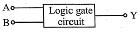
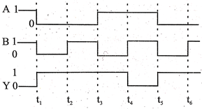
The following figure shows a logic gate circuit with two inputs A and B and the output Y. The voltage waveforms of,  and Y are as given:
The logic gate is:
Text Solution
Verified by ExpertsThe correct answer is:
D
It is clear from the given logic circuit that the output Y is low when both the inputs are high otherwise it is high. Thus logic circuit is NAND gate.
Prepare Smarter with CGP Edu
Get practice questions, solutions, and test series in one place.
Write a Review
Share your experience with this question and solution.
Commentary
Send your comment, doubt, correction, or feedback to admin.
Similar Questions
Explore conceptually related problems
Given below are symbols for some logic gates
The XOR gate and NOR gate respectively are
Given below are four logic gate symbol (figure). Those for OR, NOR and NAND are respectively
The combination of ‘NAND’ gates shown here under (figure) are equivalent to
The truth table shown in figure is for
ABY001010100111
For the given combination of gates, if the logic states of inputs A, B, C are as follows A = B = C …
Boolean algebra is essentially based on