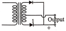
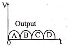
A full wave rectifier circuit alongwith the output is shown in figure. The contribution(s) from the diode 1 is (are)
Text Solution
Verified by ExpertsThe correct answer is:
B
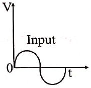
During the positive half cycle of input, the upper diode gets forward biased and conducts current while lower diode 1 gets reverse biased and does not conduct current. During the negative half cycle of input, diode 1 gets forward biased and conducts current, So the contributions from diode l are B, D type.
Prepare Smarter with CGP Edu
Get practice questions, solutions, and test series in one place.
Write a Review
Share your experience with this question and solution.
Commentary
Send your comment, doubt, correction, or feedback to admin.
Similar Questions
Explore conceptually related problems
A silicon specimen is made into a -type semiconductor by doping on an average one indium atom per …
The value of the resistor , needed in the de voltage regulator circuit shown here, equals
In the given circuit, the potential difference between A and B is
Two identical p-n junctions may be connected in series with a battery in three ways, as shown in fi…
In the circuit shown below, assume the diode to be ideal. When increases from 2 V to 6 V, the chan…
If in a junction diode, a square input signal of 10 V is applied as shown below.
Then the output…