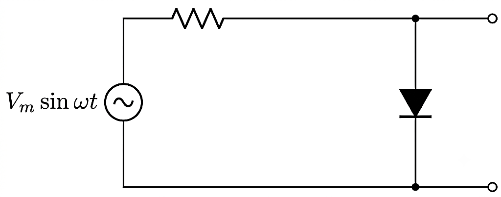
The output of the given circuit in figure.
Text Solution
Verified by ExpertsC
During positive half cycle of input ac voltage, the p-n junction is forward biased, the resistance of p-n junction is low. The current in the circuit is maximum. In this situation, a maximum potential difference will appear across resistance connected in series of circuit. Due to it, there is no output voltage across p-n junction.
During the negative half- cycle of input ac voltage, the p-n junction is reverse biased. The resistance of p-n junction becomes high which will be more than resistance in series. Due to it, there will be voltage across p-n junction with negative cycle in output.
Prepare Smarter with CGP Edu
Get practice questions, solutions, and test series in one place.
Write a Review
Share your experience with this question and solution.
Commentary
Send your comment, doubt, correction, or feedback to admin.
Similar Questions
Explore conceptually related problems