Published by:
CGP EDU Academic Team
Published on: September 13, 2026
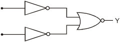
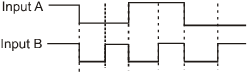
The logic circuit shown below has the input waveforms ‘A’ and ‘B’ as shown. Pick out the correct out put waveform.
A
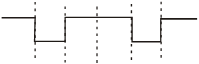
B
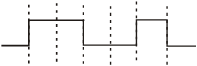
C
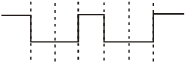
D
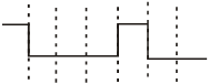
Text Solution
Verified by ExpertsThe correct answer is:
D
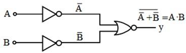
The output will be of AND gate.
A | B | |
0 | 0 | 0 |
0 | 1 | 0 |
1 | 0 | 0 |
1 | 1 | 1 |

The output will be high only when both the inputs are high.
Prepare Smarter with CGP Edu
Get practice questions, solutions, and test series in one place.
Write a Review
Share your experience with this question and solution.
Commentary
Send your comment, doubt, correction, or feedback to admin.
Similar Questions
Explore conceptually related problems
A silicon speciman is made into a P-type semi-conductor by dopping, on an average, one Indium atom …
The typical ionisation energy of a donor in silicon is
A 2V battery is connected across the points A and B as shown in the figure given below. Assuming th…
The diode used in the circuit shown in the figure has a constant voltage drop of 0.5 V at all curre…
For a transistor amplifier in common emitter configuration for load impedance of 1 k Ω Ω (h fe = 50…
In semiconductor the concentrations of electrons and holes are 8 × × 10 18 /m 3 and 5 × × 10 18 /m …