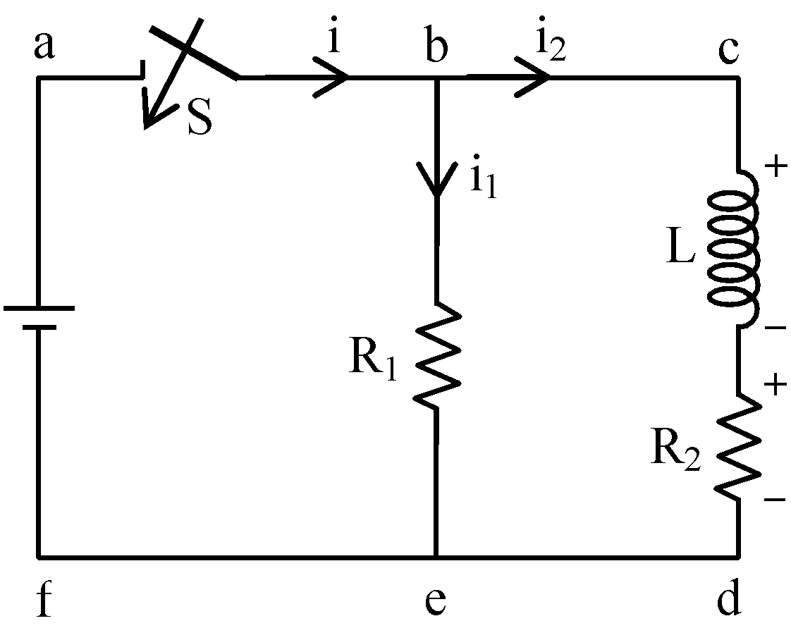
An inductor of inductance L = 400 mH and resistors of resistances R 1 = 2 Ω and R 2 = 2 Ω are connected to a battery of emf E = 12 V as shown in Fig. The internal resistance of the battery is negligible. The switch S is closed at time t = 0. What is the potential drop across L as a function of time? After the steady state is reached the switch is opened. What is the direction and the magnitude of current through R 1 as a function of time?
Text Solution
Verified by ExpertsCHECK THE SOLUTION.
Sol. Let the current distribution in the circuit be as shown in the figure.
From KCL, i = i 1 + i 2 ….. (1)
Applying KVL in loop acdfa, traversing the circuit clockwise, beginning at left corner,
E – L  – i 2 R 2 = 0 ….. (2)
which on rearranging gives
 =
=  dt ….. (3)
On integrating the eqn. (3), we get
I 2 =  [1 – e –R2t/L ]
Note that loop acdfa is a simple RL circuit with time constant L/R 2 . In the steady state, the inductor is short circuited, resistors R 1 and R 2 are in parallel arrangement. So i 1 = E/R 1 , i 2 = E/R 2 .
Potential drop across inductor
| V L | = L  = Ee –R2t/L On substituting numerical values, we have
τ L =  =
=  = 0.2 s
Steady state current, I 2 =  =
=  = 6 A
= 6 A
I 2 = 6(1 – e
–5 )
| V L | = Ee –R2t/2 = 12e –5 When the switch is opened the loop abefa is an open circuit, current in R 1 is zero instantly while in loop bcdeb the current decays to zero. Time constant of this loop is
 =
=  =
=  = 0.1 s
Current through R 1 at any time t is
i = i 0 e
–t/ 
i = 6e –10t
Prepare Smarter with CGP Edu
Get practice questions, solutions, and test series in one place.
Write a Review
Share your experience with this question and solution.
Commentary
Send your comment, doubt, correction, or feedback to admin.
Similar Questions
Explore conceptually related problems