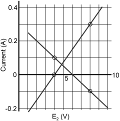
In the circuit given below, both batteries are ideal. Emf E 1 of battery 1 has a fixed value, but emf E 2 of battery 2 can be varied between 1.0 V and 10.0 V. The graph gives the currents through the two batteries as a function of E 2 , but are not marked as which plot corresponds to which battery. But for both plots, current is assumed to be negative when the direction of the current through the battery is opposite the direction of that battery's emf. (direction of emf is from negative to positive)
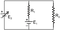
(i) The value of emf E 1 is
Text Solution
Verified by ExpertsCHECK THE SOLUTION.
[(i) b, (ii) b, (iii) d]
Sol. As E 2 is increasing it's current also increases, So, increasing graph is of i 2 .
i 1 = 0.1A, E 2 = 4V, i 2 = 0
As 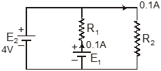
0.1 R 1 + 0.1 R 2 – E 1 = 0
0.1 R 2 – 4 V = 0
R 2 = 40 Ω Ω
Now i 2 = 0.3A, i 1 = – 0.1 A, E 2 = 8V
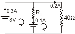
Now vc ; 0.1 R 1 +E 1 – 8 = 0
When E 2 = 6V, current in E 1 is i 1 = 0(from graph)
E 1 = 6V
R 1 =  = 20 Ω Ω
Prepare Smarter with CGP Edu
Get practice questions, solutions, and test series in one place.
Write a Review
Share your experience with this question and solution.
Commentary
Send your comment, doubt, correction, or feedback to admin.
Similar Questions
Explore conceptually related problems