Published by:
CGP EDU Academic Team
Published on: September 12, 2026
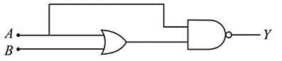
The truth table for the circuit given in the fig. is :
A

B

C

D

Text Solution
Verified by ExpertsThe correct answer is:
C
A | B | |||
0 | 0 | 0 | 0 | 1 |
0 | 1 | 1 | 0 | 1 |
1 | 0 | 1 | 1 | 0 |
1 | 1 | 1 | 1 | 0 |


Prepare Smarter with CGP Edu
Get practice questions, solutions, and test series in one place.
Write a Review
Share your experience with this question and solution.
Commentary
Send your comment, doubt, correction, or feedback to admin.
Similar Questions
Explore conceptually related problems
Mobility of electrons in a semiconductor is defined as the ratio drift velocity to the applied elec…
Ge and Si diodes start conducting at 0.3 V and 0.7 V respectively. In the following figure if Ge di…
To get output ‘1’ at R, for the given logic gate circuit the input values must be
For the circuit shown below, the current through the Zener diode is :
In the given circuit the current through Zener Diode is close to :
The circuit shown below contains two ideal diodes, each with a forward resistance of 50Ω. If the ba…