Published by:
CGP EDU Academic Team
Published on: September 13, 2026
The following figure shows a logic gate circuit with tow inputs A and B and the output C. The voltage waveforms of A, B and C are as shown below -
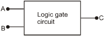
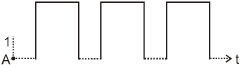
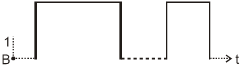
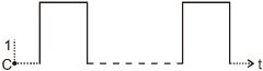
The logic circuit gate is :-
Text Solution
Verified by ExpertsThe correct answer is:
A
Gate is  gate.
gate.
Because
A | B | C | |
interval | 0 | 0 | 0 |
interval | 0 | 1 | 0 |
interval | 1 | 0 | 0 |
interval | 1 | 1 | 1 |


Hence this is  gate.
gate.
Prepare Smarter with CGP Edu
Get practice questions, solutions, and test series in one place.
Write a Review
Share your experience with this question and solution.
Commentary
Send your comment, doubt, correction, or feedback to admin.
Similar Questions
Explore conceptually related problems