In the circuit shown in Fig., R 1 = 8 Ω , R 2 = 5 Ω , C 1 = 6µF, C 2 = 3µF, E 1 = 5V, r 1 = 2 Ω , E 2 = 24V, r 2 = 3 Ω , E 3 = 14V and r 3 = 2 Ω .
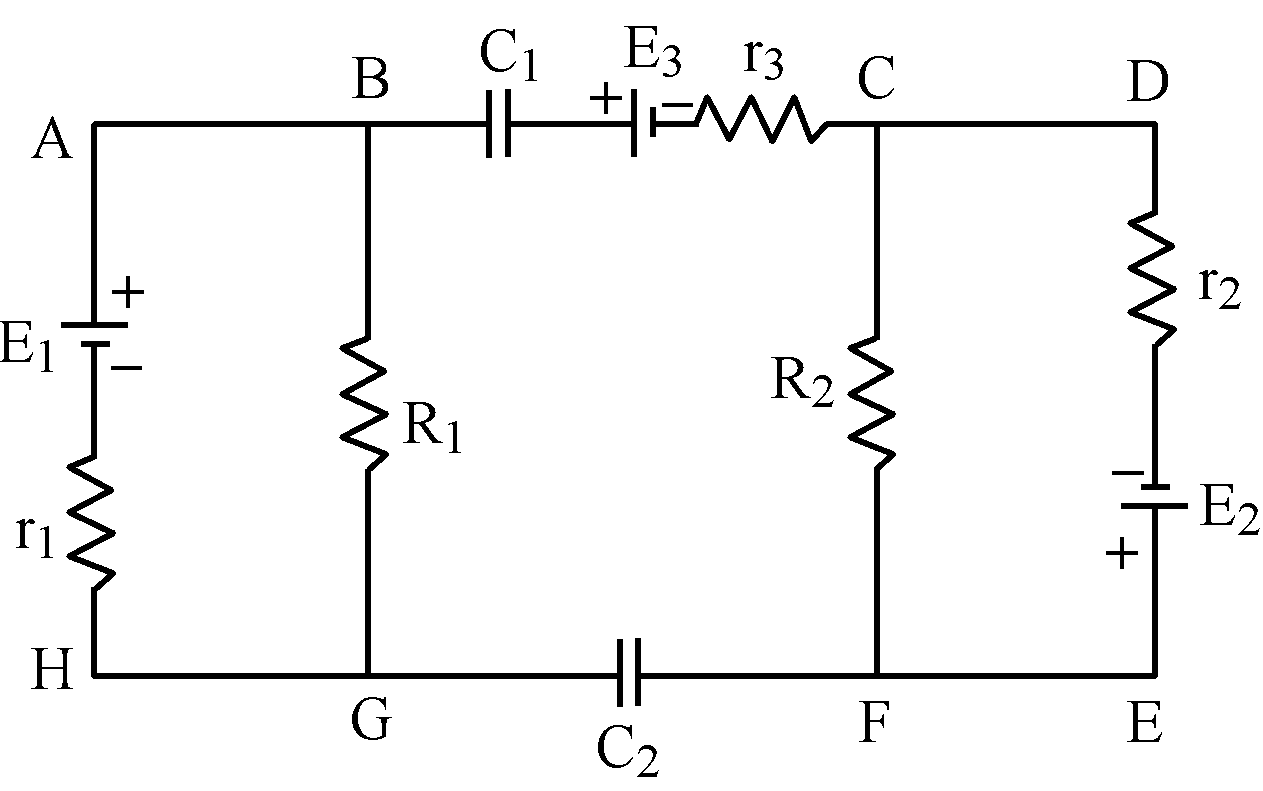
Calculate charge on capacitors C 1 and C 2 in steady state.
Text Solution
Verified by ExpertsCHECK THE SOLUTION.
Sol. In steady state, no current flows through capacitors, therefore, there are four unknown quantities in the given circuit:
(i) current in left mesh ABGHA,
(ii) current in right mesh CDEFC,
(iii) charge q 1 on capacitor C 1 and
(iv) charge q 2 on capacitor C 2 .
But by applying Kirchhoff's voltage law three unique equations can be formed. It means that one more equation is required to analyses the circuit.
Considering the circuit at an instant when steady state was not reached and charges on capacitors were increasing. By applying Kirchhoff's current law at junctions, it is found that currents through two capacitors were always identical as shown in Fig. . Hence, magnitudes  and
and  of charges on two capacitors are equal. Let it be q.

Fig.
From directions of current in Fig. , it is clear that if left plate of capacitor C 1 is positively charged then right plate of capacitor C 2 , will be of the same polarity. Considering this fact, in steady state, circuit will be as shown in Fig. .
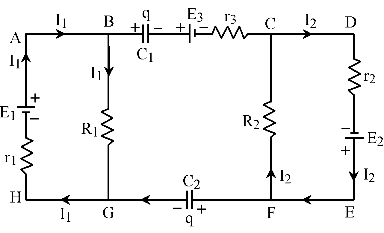
Fig.
Applying Kirchoff's voltage law on mesh ABGHA,
I 1 R 1 + I 1 r 1 – E 1 = 0 or I 1 = 0.5 A
From mesh, CDEFC, I 2 r 2 – E 2 + I 1 R 2 = 0 or I 2 = 3 A
Now applying Kirchhoff's voltage law on mesh BCFGB,
+  + E 3 – I 2 R 2 +
  – I 1 R 1 = 0
q = 10 µC
Prepare Smarter with CGP Edu
Get practice questions, solutions, and test series in one place.
Write a Review
Share your experience with this question and solution.
Commentary
Send your comment, doubt, correction, or feedback to admin.
Similar Questions
Explore conceptually related problems