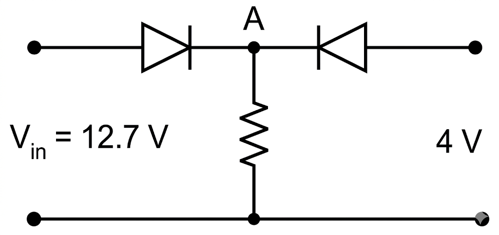
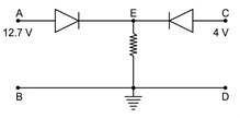
Both the diodes used in the circuit shown are assumed to be ideal and have negligible resistance when these are forward biased. built in potential in each diode is 0.7V. For the input voltages shown in the figure, the voltage (in volts) at point A is .
Text Solution
Verified by ExpertsThe correct answer is:
CHECK THE SOLUTION.
(12)
Let 
Right diode is reversed biased and left diode is forward biased

 Volt
Volt
Prepare Smarter with CGP Edu
Get practice questions, solutions, and test series in one place.
Write a Review
Share your experience with this question and solution.
Commentary
Send your comment, doubt, correction, or feedback to admin.
Similar Questions
Explore conceptually related problems