The following figure shows a logic gate circuit with two inputs  and
and  and the output
  . The voltage waveforms of
  and
and  are given
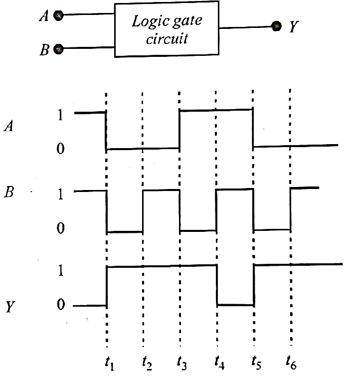
The logic gate is :
Text Solution
Verified by ExpertsThe correct answer is:
A
From the given waveforms, the truth table is as follows.
1 | 1 | 0 |
0 | 0 | 1 |
0 | 1 | 1 |
1 | 0 | 1 |


The above truth table is for NAND gate.
Therefore, the logic gate is NAND gate.
Prepare Smarter with CGP Edu
Get practice questions, solutions, and test series in one place.
Write a Review
Share your experience with this question and solution.
Commentary
Send your comment, doubt, correction, or feedback to admin.
Similar Questions
Explore conceptually related problems
PHYSICS
SINGLE CORRECT MCQ
If the nuclear radius of is , the approximate nuclear radius of in fe…
A resistance of is connected to a source of an alternating potential . The time taken by the curr…
The equation of a wave on a string of linear mass density is given by
The tension in the string i…
Two bodies of mass and have position vectors and respectively. The magnitude of position vector…
At what distance from a long straight wire carrying a current of will the magnetic field be equal …
An ideal gas is initially at is expanded to and then compressed adiabatically to the same volume …