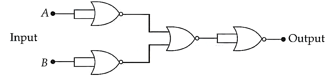
The given circuit works as :
Text Solution
Verified by ExpertsThe correct answer is:
B
Let the inputs be A and B. The circuit is composed of NOR gates.
A NOR gate with its inputs tied together acts as a NOT gate.
The output of the first NOR gate (input A) is  .
.
The output of the second NOR gate (input B) is  .
.
These outputs are fed into a third NOR gate. Its output is  .
.
Using De Morgan's theorem,  .
.
This output  is the input to the fourth NOR gate, which is configured as a NOT gate.
The final output is 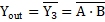 .
.
The expression  represents a NAND gate.
Prepare Smarter with CGP Edu
Get practice questions, solutions, and test series in one place.
Write a Review
Share your experience with this question and solution.
Commentary
Send your comment, doubt, correction, or feedback to admin.
Similar Questions
Explore conceptually related problems
The following diagram shows a Zener diode as a voltage regulator. The Zener diode is rated at and …
Identify the correct truth table of the given logic circuit.
ABY001010101110
ABY001011101110
ABY0…
The correct truth table for the given input data of the following logic gate is :
110100011010101…
Find the correct combination of and D inputs which can cause the LED to glow.
For the given logic gate circuit, which of the following is the correct truth table?
000011110101…
Assuming in forward bias condition there is a voltage drop of 0.7 V across a silicon diode, the cur…